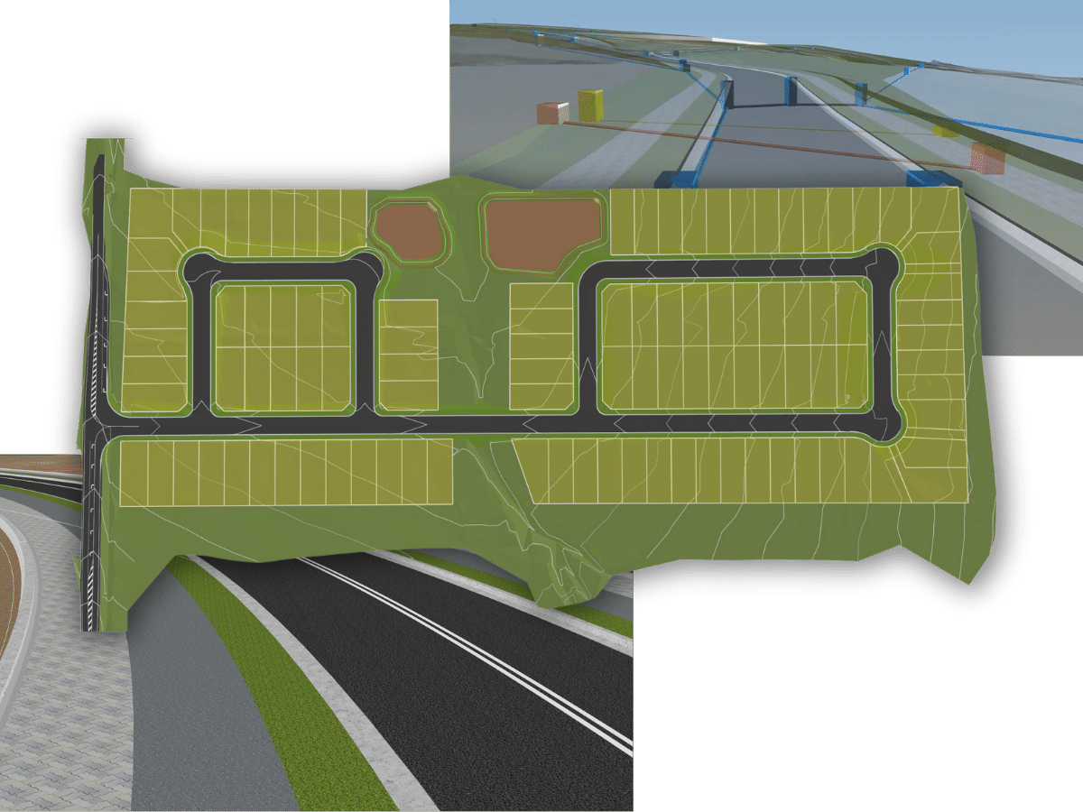

Road Design, Pipe and Channel Tools for every project
Key features for Road Design – Highway Design, Rural Roads, Subdivision road networks
Surface creation is quick and easy with support for multiple data inputs, intuitive display controls and outputs dynamically represented directly inside the drawing, ready for plotting and publishing.
The Surface model inputs support external point data and Land XML files as well as reading 3D data directly from the drawing. Surface display controls are immediately accessible to you, allowing for fast and dynamic adjustments to contour intervals, colours, layers, contour labelling and surface analysis.
Analyse your surface with tools to show elevation banding, slope ranges, directions and slope arrows coloured to your design requirements. Create tables of your surface analysis as AutoCAD tables, ready for plotting and publishing.
LandXML file transfer is fully supported so surface data can be imported and exported readily across multiple design platforms. Create and edit your surfaces in Civil Site Design with the confidence of being able to immediately share that information with the broader design community.
Surface objects can be selected by mouse click in the drawing and edited. Surface data can also be exported to AutoCAD entities as desired, for sharing with any AutoCAD user.
Obtain volume reports between any two surfaces, including accounting for compaction factors and applying height adjustments. Volume reports can be exported to a text file for re-use in the drawing and for other documentation purposes.
Built for rapid design of features such as building pads and detention basins, the dynamic grading tools automatically clean up internal overlapping corners and include radial and mitre options on external corners.
With the Site Grading tools you can take a polyline, apply a cross section template (assembly) to create a graded surface complete with corner cleanup. The surface and grading linework automatically updates as you edit your grading, so you get immediate feedback on the impact of your design changes, as you make them.
You can immediately review volume outputs after making design changes, enabling easy volume checking and optimization. Use the Civil Site Design Surface Modelling tools to create one total dynamic surface model incorporating all your land development components – perfect for lot grading.
It’s simple and easy in Civil Site Design – draw a polyline and click to turn it into an alignment object. Labelling is fully automatic and user customisable as is the line, arc and spiral display.
Alignments can be easily edited during the creation process or via the alignment editing tools – users just click to edit an IP and get access to tools to change the spiral lengths, curve radius and IP position. Add IP’s, delete and move IP’s within the one editing environment.
When you make an edit to the alignment geometry the display updates in the drawing, including the labelling.
Label display is customizable by you, with a simple interface for the addition of blocks, arrows, lines, circles and text in the chainage labelling, on user defined AutoCAD layers. In AutoCAD, labels react with the drawing scale in model space so there is less work trying to get the size right for plotting, and labels flip to be plan-readable in the model. Set your own standards for labelling including sampling intervals for major and minor chainages.
Create alignment tables when you create or edit your alignment. You select the information to include in Alignment Tables and Curve Tables and then generate AutoCAD tables at the click of a button. As part of the editing process the AutoCAD tables can be updated in the drawing after the geometry of the alignment changes.
As changes are made to the design, the drafting updates in your drawing, ready for plotting and publishing.
Data share is made easy via Land XML transfer. Import and export alignment geometry across multiple design platforms.
Key features for Road Design
- Combines template and string-based design
- Comprehensive string design tools for complete section control
- Centralised vertical grading and section tools to streamline the design process
- Automates common road network elements such as intersections, kerb returns, cul-de-sacs and knuckles
- Dynamic and interactive views for profiles, section, plan design and fully rendered 3D model view for analysis
- Multiple vertical design and section windows to view the design at various chainages, with trackers in each
- Publish long and cross section views, point set-out and tables
Complete your pipe designs and generate your design outputs directly in the drawing, using polylines to create your networks. Interactive vertical design windows make designing the pipe branches simple. See the pipe details in pipe profile views including all crossing services and highlighting conflicting pipes. Stormwater designers can assign catchments and rainfalls, automating pipe inverts and pipe sizes using Rational Method design flows.
Civil Site Design includes an optional HEC-RAS menu which provides users with the ability to transfer section data to HEC-RAS for river analysis, including assignment of Mannings coefficients, defining overbank areas, skewed sections, houses and ineffective areas.
Waterline results from HEC-RAS can be exported back to Civil Site Design for presentation in the drawing and construction of a water surface.


